Radical Computer Technologies FPiGA Audio Hat
Board Diagram

Crimson 1.0.0 Release Notes
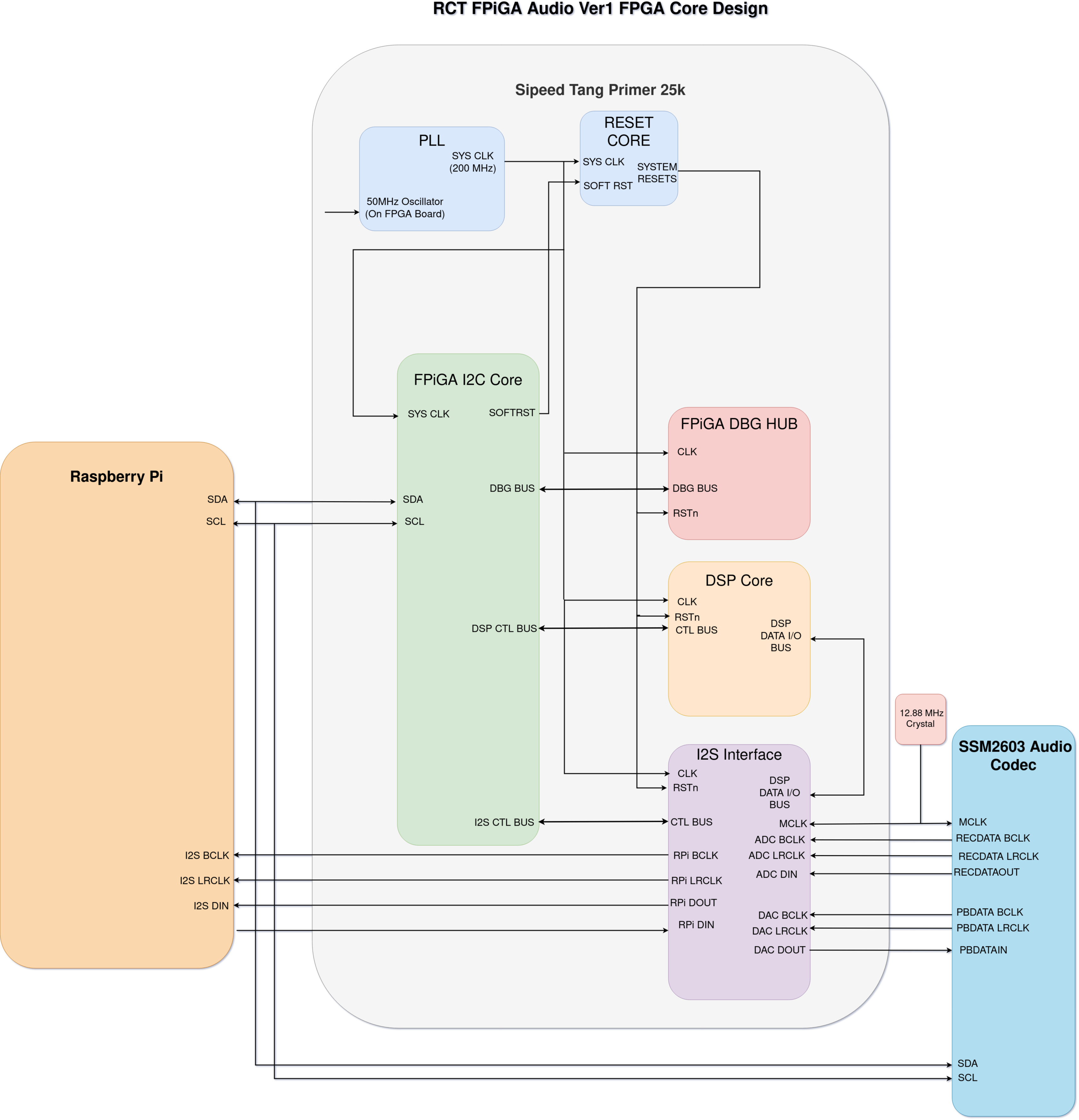
A basic diagram of the system design is below:
Core Design Features
- I2S clocks generated from the SSM2603 codec
- High speed DSP FPGA system clock generation from Gowin PLL
- CDC between I2S interface to DSP core to move from BCLK domains to FPGA System clock domain and from System clock to BCLK domains
- Raspberry Pi ALSA device tree overlay + dtsi source. Allows for driving the Pi’s audio system to send and receive data.
- FPGA I2C Register bank implementation for control from the Raspberry Pi
- DSP Core which enables <1 sample latency processing of Audio samples
- Waveform generation from FPGA
- Integrated Mixer in FPGA
- Control of codec programmable gains in FPGA
Planned Features
- Programmable Biquad filter bank
- Programmable signal path generation via rudimentary instruction set (Similar to SPIN FV-1)
- Delay effect
- Oversampling filters
- Bitcrushing
Supported Platforms
- Raspberry Pi 3, 4, 5, CM4, CM5, Zero, Zero 2 W,
- Rock Pi 3C, Rock Pi Zero 3W, Rock Pi CM3, and Rock Pi 5. (Planned)
- Orange Pi Platforms (Planned)
Building
FPGA Build
The FPGA project source can be built using the Gowin EDA Toolset. All source for this can be found in the hw_rev1_0/source/hdl directory.
Raspberry Pi Source
Device Tree Overlay
We include a prebuild device tree overlay for the Pi 4 under hw_rev1_0/source/devicetree .
Building this for other Pi platforms can also be accomplished by using the device tree compiler to compile the included .dtsi file.
From here you will need to install the overlay and modify the /boot/firmware/config.txt file to utilize the compiled overlay on boot.
Library and Examples
Source for the userspace library and examples can be found in the hw_rev1_0/source/userspace folder. Copying this folder to the Raspberry Pi and running the included buildall.sh file will build all source and examples.